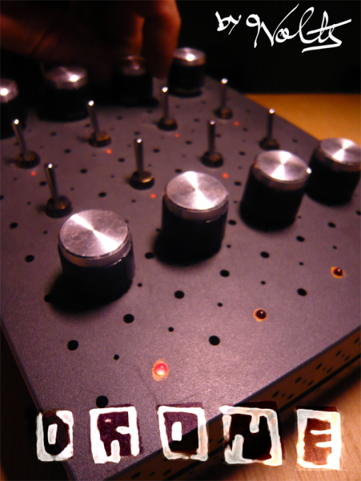
DRONE sounds SYNTH, cased inside an old router box. Chaotic but under control.
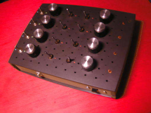
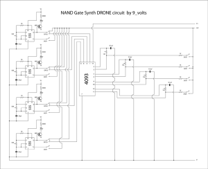
The circuit for this instrument is quite simple, four 555 in astable configuration gating and four oscillators made with just one 4093.
The interface is arranged as four channels across,each one has three switches and two potentiometers, and LED showing it’s state:
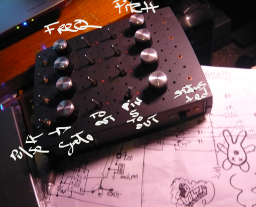
So for each channel, the first pot (50k) controls the freq of pulse coming out from the pin3 of each 555; this signal can be routed to main out (resulting on a pulse beating oscillation) or to gate each of the 4 oscillators made with the nand gates of the 4093. the second pot (1M) controls the pitch of the gated oscillators on IC 4093. the switches allow for some tweaking on each channel, either pulse ore gated/osc mode,also the indispensable channel on/off, and finally the third switch connects the pins 5 of the 555 (voltage control?) to the main out resulting on some interesting broken rhythmic patterns…for some magic of electronic randomness…All switches positions can be use combined into several different modes,and like always (I’m not an engineer) the oscillators affect and modulate each other..sometimes beautiful harmonies occur inside the rhythmic pattern…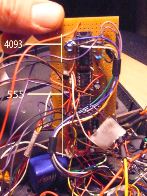
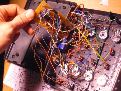
The result is an instrument that is fun to play, because while it has it’s random magic sound remains totally controllable.
Here is a video of the DRONE in action performed by 9volts & ChairB and recorded by LucySombra.
video of PyR 2009 | PyRformance Alba G. Corral + Nikka
Nikka is owner and user of Drone Synth
31 Comments
hi,
it’s very amazing..
do you sell your drone synth?
thanx
elia
hey thanks for your words
well i don’t sell my prototypes but if you pay for the components and some for the work i could make you one,,,it’s actually pretty simple design a little tedious to build but all the info to build it is in my blog so if you are handy you can also build it yourself and save some money, i can help you with doubts….
well anyway thanxs again as I said i don’t have a shop… yet!
9volts
We sell a similar drone synth with CV and Clock inputs at synthrotek.com. We see them as kits from PC Boards to Fully assembled. Hope this helps!
Steve
wow really interesting kits…i am looking forward for your 16 step seq and control boards info… good job!! 9volts
What size breadboard did you use? I want to try making this.
the one i use is 14.5 x 17 cm…
Thank you for the quick reply. I was wondering if you happen to have the layout you used on the breadboard.
I do not seem to have the knack of using the space efficiently and I would love to see how you have it laid.
Also, is the NPN transistor a specific type/model number? (I am still new to electronics)
And lastly, where are the led’s placed in the circuit?
Thanks!
i do not have pictures of prototyping process…but basically start placing the ic’s with enough space arround them and then place the components that connect to ground and vc…and the use jumper wires to replicate rows on less populated areas of the breadboard for the rest of components…for example the (transistor resistor led) sections can be alocated away of the ic’s…i recomend you to print the diagram and then place each component over the print, so you can go implementing them on the breadboard in a more organized way… on the other hand i think i used bc547 for the npn..not 100%sure but give it a try…any common npn should work anyway…i do not have the prototype..but i plan on building some more when i do i will take some pictures….and post them
good luck
do you have voltage ratings on the capacitors?
also power ratings for resistors?(i just assume its a quarter watt but asking just to be sure)
thanks
yes it will be fine
9v
Hey, I just stumbled upon this magnificent thing on the Internet, and I really want to put one together myself.
I’ve been looking at your diagram, and I THINK I have all the parts required.
Please, correct me if I’m wrong, I don’t want to spend money on the wrong components, haha.
4x LM555CN Timers
1x CD4093
4x 2N2369 NPN
4x 0.1uF 50v Ceramic Capacitors
4x 22uF 50v Radial Electrolytic Capcacitors
8x 1k 1/4W Resistors
4x 50k Linear Pot
4x 1M Linear Pot
4x 560ohm 1/4W ( I tried looking for 600ohm, but the closest I could get was 560. )
8x SPDT on-on Toggle Switch
4x DPDT on-off-on Toggle Switch
I’m pretty new to this whole electronics ordeal, but this doesn’t seem too hard to put together – just very time consuming. I hope to hear from you soon!
seems to me at first glance that your list is ok, don’t worry about the resistors exact value as far as you get matching 560ohms it will be ok. it has been a long time since i did the synth drone myself so it is nice to see renewed interest on the circuit please make sure to share your progress , i will be happy to see how it comes out… thanks and good luckr from 9v
It may be a bit late, but i believe all you need is an Audio out jack, and a power source.
I Plan on building this as a weekend project. I love droney sounds and ambient noises. I was just wondering where do you connect the audio out jack to? Do you connect it to where it says V+ and Out? Or to where it says Out and to the ground?
On another note, i absolutely love you city.
Hi,
I would like to ask you, whats the difference between [V-] and [GND] … Like, you mean the same thing probably I guess? Or are you using symetric inverted power supply?
Thanx a lot for your answer, I am trying to build one because I think that the way how you use NAND to mix up 555clock is really awesome.
You’ve got my respect, I really like your projects…
first thanks for your words.. second i was just using a 9v battery to power the circuit, so yeah i meant the same for gnd and V-.. hope you enjoy the nandroning…
Where do the other lines of the pots go?
an image better than a 1000 words:
sorry i might had used a little confusing symbology on the schematic..
and i recomend you this link check out the wole site it is full of great info
Hi,
I first of all, thank you. The device seems to be interesting. I decided to try to build myself a copy of the synthesizer.
555 Oscillators are working well. But the NAND circuit connections is a problem. Probably the fault is 1M potentiometer coupling. I do not get it.
Can you help a little?
Iam building a similar NAND drone but iam using a TTL Nand chio instead of the CMOS 4093, namely the 74LS00, and instead of 4 555, iam gonna use 2 556 chips. iam hoping it works ince ive been having a bit of a problem with the NAND oscillators modulating each other probabaly since thay have common gnd and +5 v rails.
I built this off the schematic a couple weeks back. It should be noted that it sounds much less muddy with diodes (or possibly resistors) on all the 555 to speaker outputs
I agree that paired resistors would be the way to go.. I did add a mini mixer circuit on my second version of the drone, never documented it yet but it is more controlable and way healthier for the speaker amplifier!! Thks for your comment
Hi 9volt , this is awesome mashine, thank a lot for info, but i have a problem, a took 2N2222A and they burn in 20 seconds..((( tec specs is just like BC547 even a little more powerful, but just a little) what should i try to change? Please help me 🙂 …and thanx again for the lot of useful information!! Good luck!
Could be that you placed the transistor backwards because checking both datasheets their pin configuration is reversed..??
On Sunday, May 11, 2014, hacked circuits by 9volts wrote:
>
no, i checked twice, today i try to use big russian npn`s кт819г – as result: npns hot and nothing work( i even try to place it backward – nothing chages…
Assuming you are breadbording the circuit check for shorts between rails where the transistor is placed Good luck
On Monday, May 12, 2014, hacked circuits by 9volts wrote:
>
Tnx! I decide to cut leds from circuit with npns )))) radically but effective) Good luck to you too and thanks for quick answers, i really appreciate this!
Ok hope you enjoy…thks
On Tuesday, May 13, 2014, hacked circuits by 9volts wrote:
>
Hi !
Beautyful drone synth
I try to make it. But i dont understand the conections with the electrolytic capacitors.
I mean, the symbology , what part is negative and what part is positive.
Because the IC NE 555 in the N°1 conect to the capacitor and the negative volt (-9v) but the symbology on the capacitor say positive. is correct.
Its right ?
Please tell me if its ok to start the work.
Really thanks for this post.
And sorry for my english
Looks great! Any chance of a strip/matrix/veroboard design?
Wow! Must build this!
I have my own versions : youtube.com/weapea